LED Cube Project
So I was watching Weekend Projects a about two and a half months ago and saw how to make a 3 by 3 by 3 LED cube. I thought, “Hey! I could do that with my Arduino!” and I did. Basically, I can turn any individual LED on or off.

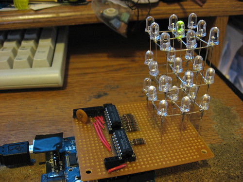
I started with soldering together the LEDs in layers of nine. Then I played around with how to wire up a protoboard with two Shift Registers on it and the LEDs to make a Shield for the Arduino. The first try was messy. The second try was better but not ideal. The final wiring guide may LOOK messy, but it’s basically what I used.
The final wiring on the protoboard from the bottom is the last photo.
The software was a compilation of the original software from the Weekend Projects post and the ShiftOut example on Arduino.cc. I started with the “Code Sample 2.3 – Dual Defined Arrays” at the bottom of the ShiftOut example and slowly stirred in the original code to produce the final result. Here is the final code.
Here’s a link to the Flickr photos.
P.s. On a side note, I did the layout and wiring wrong so I had to modify the code to compensate for the LEDs being connected wrong.


hello, nice work!
how do you connect the LEDs (anodes and cathodes) in the grid?
Featured on HacknMod’s Top 40 Arduino Projects of the Web:
http://www.hacknmod.com/hack/top-40-arduino-projects-of-the-web/
Hi Tim, I’m Cristobal from Chile, I am writing because I’m a long time looking for a 3d cube with arduino, but I have some questions :) the resistance Ω(I don’t know as it is called in english) that you used what band is Ω? and you use 74MC595, is this a micro processor? You could give me more information? you used something front to HD1, what is? please!!
thanks and sorry for my english
Hi Cristobal,
The resistors are 150Ω the color bands are Brown – Green – Brown – Gold.
The two ICs on the board are 74HC595. They are not micro processors, they are Shift registers which take serial input from the Arduino and output to 8 separate(parallel) outputs to control the power to each column. The grounds of each of the three levels are connected with wire without insulation directly to Arduinos pins 6, 12 and 11.
The thing connected to HD1 is a 0.1 uF capacitor. I got the information for it from http://www.arduino.cc/en/Tutorial/ShiftOut it said “Notice the 0.1�f capacitor on the latchPin, if you have some flicker when the latch pin pulses you can use a capacitor to even it out.” The other thing that is connected above HD1 and next to IC1 is another connector to connect to the Arduinos pins 6 and 7.
Good luck!
-Tim
hello, I tried your program with two STP08CP05 drivers which are pretty similar to the 74HC595 but it does not seem to work and I’m wondering why. Also, I understand that all the bits set to 1 will light up all the leds and 0 will turn them off but i dont get the other combinations and their functions like 110 or 101 in the code for the pattern. Can you please enlighten me on the programming block for the pattern? I’d also like to know if you would know how to make it work with STP08CP05 drivers.
Thanks!
Following your code and the third drawing of your circuit, nothing comes out of Q0 on IC1 and the last 2 anodes on IC2 come out from Q6 and Q7. With your code, how do you control the outputs of the data?
Thank you for the detailed info. I’m waiting (impatiently) for my first Arduino from Amazon… I have some work to do on my soldering skillz, but plan to follow your steps as my *first real* project.
Nice blog, but seriously, the amount of Ads really make the readers experience much lower.
Thanks for the comment Abdul-Wahid, but I have no ads on my site at all, so I’m kind of confused about your comment.
-Tim